
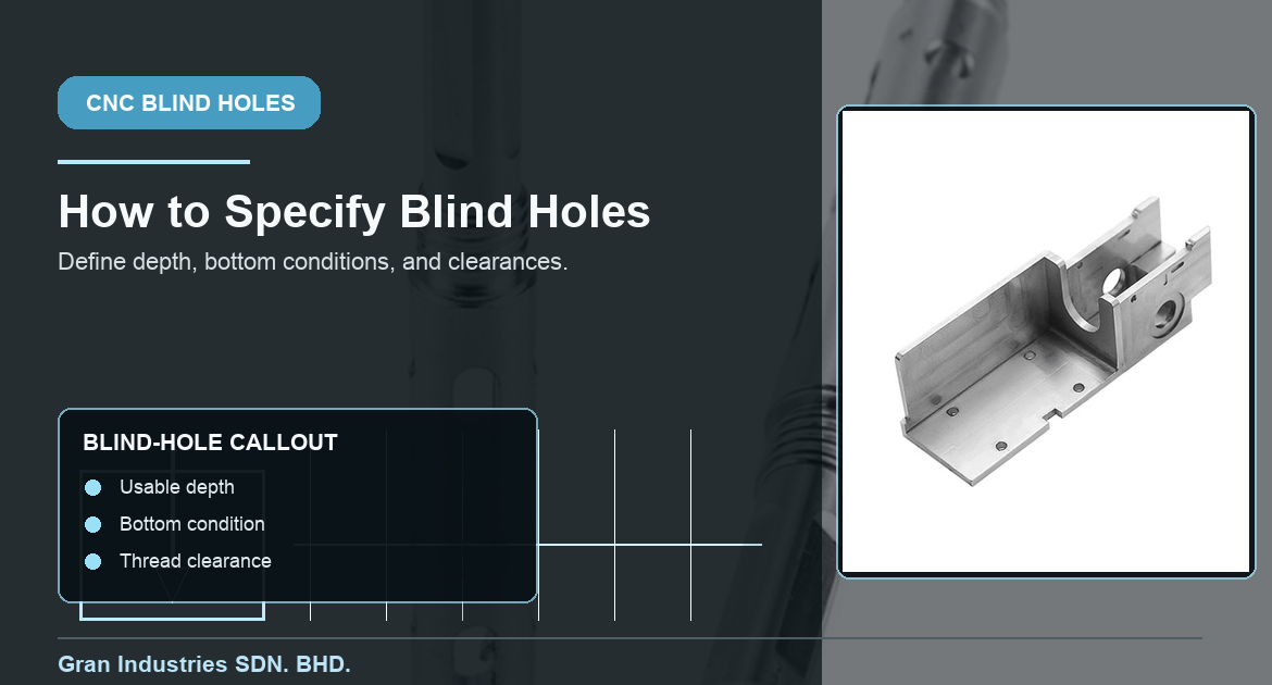
Blind holes are common in custom CNC machined parts, but they are often specified with less detail than the function requires. A drawing may show a diameter and a depth without stating whether the depth is measured to the drill point, to a full-diameter section, to the start of a thread, or to the bottom of a counterbore. That ambiguity can lead to an avoidable mismatch between the part that is manufactured and the part that needs to assemble.
A clear blind-hole callout does not need to be complicated. It needs to communicate the functional depth, the expected bottom condition, the relevant datum or location tolerance, and any clearance needed for a fastener, mating component, or fluid path. These details let the machining team choose a practical drilling, milling, boring, or tapping sequence before production begins.
At Gran Industries, blind holes are reviewed as part of the complete feature, including how they are accessed, how they will be measured, and what the assembly actually needs. The goal is to make the drawing clear enough that the quote and machining plan do not depend on guesswork.
Start by defining what the depth means
Depth is the most important point in a blind-hole callout. A conventional drill creates a conical point at the bottom, so the overall drilling depth is not always the same as the depth available to a mating pin, screw, thread, or flat-bottomed component. If the functional item must seat near the bottom, the drawing should state the usable depth rather than assuming the drill point is usable space.
Before finalizing the drawing, confirm:
- Whether depth is measured to the tip of the drill or to the full-diameter cylindrical portion
- Whether a mating component needs clearance at the bottom
- Whether the feature is plain, reamed, bored, tapped, counterbored, or used for a dowel pin
- Whether the bottom must be conical, flat, radiused, or relieved
- Whether the depth applies before or after coating, finishing, or another secondary operation
That information is more useful to a CNC shop than a deep nominal hole dimension alone. It describes the part’s functional requirement and lets the team select the correct tool sequence.
Distinguish drill depth from usable depth
For a plain drilled blind hole, the drill point normally extends below the full-diameter portion of the hole. If a screw, pin, or locating feature must reach a specific depth, leave practical clearance below the functional engagement zone. The amount of clearance depends on the tool, diameter, material, and feature type, so the drawing should communicate the needed function instead of requiring a generic point geometry.
For tapped blind holes, the distinction is even more important. The drilling depth, tapping depth, and full thread engagement length are separate values. A tap cannot normally produce usable threads all the way to the bottom because of its lead geometry. A callout that specifies only a thread depth may leave the required usable engagement unclear.
When the hole supports a precision location, also review it with Gran’s guide to ثقوب دقيقة and the related guidance on dowel-pin features. Diameter, location, depth, and entry condition can all affect the final assembly.
Specify the bottom condition when it matters
Not every blind hole needs a special bottom. A standard drilled point is often the most efficient and reliable option. A flat-bottom condition should be specified only when the assembly, seal, spring, component seat, or other function truly needs it. Flat bottoms may require a different tool or a finishing operation, particularly in small diameters or deep holes.
Common bottom conditions include:
- Standard drill point for non-critical clearance below the functional depth
- Flat-bottomed counterbore for a fastener head, seated component, or controlled stop
- Reamed or bored bottom region when a close-fit pin or feature needs a defined depth
- Relief or extra clearance for a thread, tap lead, debris, or a mating-part radius
- Controlled radiused condition where a sharp internal corner is neither necessary nor practical
The drawing should identify the condition that affects function. Otherwise, the shop should be allowed to use a normal manufacturable drill point rather than add cost to create a bottom detail that the part does not need.
Threaded blind holes need three separate requirements
A threaded blind hole should normally identify the thread designation, the required usable thread length, and any drill or tap clearance below that length. These are not interchangeable. The tool path needed to create the thread can extend farther than the thread that is suitable for a mating fastener, and the fastener itself may need clearance below the engaged threads.
Also state whether the fastener is expected to bottom out. In most assemblies, the clamp load should be controlled by the joint surfaces, not by the fastener reaching the end of the hole. If the fastener must stop at a particular depth, that is an assembly requirement that should be shown explicitly.
Gran’s article on threaded holes for CNC machined parts provides additional context for thread callouts, engagement, and quote preparation.
Location and datum references still apply
Blind holes are not only depth features. Their location and orientation may be critical to the part. A mounting hole can have the correct diameter and depth but still fail if it is located from the wrong face or its axis is not controlled relative to the actual assembly datum.
Use a coherent datum scheme for holes that interact with other parts. The drawing should make clear which surfaces establish the part during manufacturing and inspection. For multi-face patterns, angled holes, or features that must align with bores and locators, the process may require more than a simple coordinate dimension. The guide to خصائص نظام الإسناد وأهداف نظام الإسناد explains the role of those references in practical machining and inspection.
Deep blind holes require an access and chip-removal review
As a blind hole becomes deeper relative to its diameter, tool reach, chip evacuation, coolant access, heat, and part stiffness become more important. The practical limit depends on the material, hole diameter, machine, tool, and required finish. A deep hole may be fully manufacturable but need a different sequence, intermittent clearing, a specialized drill, or a revised tolerance expectation.
Do not assume a deeper hole is merely a longer cycle. The part may need additional support, and the process may need to account for drill wandering, chip packing, or a less accessible measurement point. When a deep hole is critical, include the intended functional depth and inspection requirement in the RFQ so the shop can plan the real process.
Inspection should match the functional callout
Inspection needs to confirm the requirement shown on the drawing. A depth gauge, pin, bore gauge, CMM, thread gauge, or custom fixture may be appropriate depending on the feature. The measurement method should distinguish between the drilled point and the usable depth if that distinction matters to assembly.
For close-tolerance or production-critical features, define whether the blind hole is part of the first article requirement, an in-process check, or final acceptance. Gran’s overview of فحص المادة الأولى explains why these priorities are best agreed before a batch is complete.
What to include in an RFQ for blind holes
A useful RFQ includes a 2D drawing and 3D model when available, material, quantity, hole diameter, functional depth, bottom condition, thread details where applicable, location tolerance, finish requirements, and any assembly constraints. If a mating fastener, pin, or component is sensitive to bottom clearance, identify that directly.
It is also helpful to state whether the hole needs a standard drill point or a controlled bottom. This gives the supplier enough information to quote the feature correctly without adding unnecessary operations.
Frequently asked questions about blind holes for CNC parts
Can a blind hole have a perfectly flat bottom?
It can be machined with a flat or near-flat bottom when the feature and tool access justify it, but a standard drilled hole naturally leaves a conical point. Specify a controlled flat bottom only when the function needs it.
How much extra depth should I allow below a threaded blind hole?
There is no universal value. It depends on thread size, tap or thread-milling method, required thread engagement, fastener geometry, and material. State the usable thread length and the needed clearance so the shop can determine a practical drilling depth.
Are deep blind holes more expensive?
They can be. Greater depth can increase cycle time, tool reach, chip-removal demands, and inspection effort. The cost impact depends on diameter, material, tolerance, quantity, and whether the bottom condition is functional.
Should blind-hole depth be measured to the drill point?
Only if the drill point depth is the functional requirement. If a mating feature needs full-diameter space or usable threads, state that usable depth separately.
Clear blind-hole notes reduce avoidable machining risk
Blind holes are straightforward to manufacture when the drawing makes the functional requirement clear. State the usable depth, bottom condition, thread engagement where relevant, datum references, and inspection priorities. This lets the CNC machining team select an efficient process and prevents avoidable assembly issues.
If your custom part includes deep, threaded, close-fit, or function-critical blind holes, send Gran your drawing and project details. We can review the hole requirements before quotation and help identify where a clearer callout will improve the manufacturing plan.