Engineering plastics are the quiet workhorses of modern mechanical design. They reduce weight, eliminate corrosion, absorb vibration, and provide electrical insulation where metals cannot. But machining them well is not simply a matter of running a metal programme with a plastic workpiece. Plastics deflect under clamping pressure, expand with heat mid-cut, and produce burrs that require a different eye than the one trained on aluminium or steel.
At GRAN INDUSTRIES SDN. BHD., engineering plastic machining is structured around four core CNC operations: turning, milling, drilling and boring, and surface handling. Each is selected based on the part geometry, fit requirements, and operating conditions the finished component will face. This article explains each method, the typical part categories it produces, and how GRAN’s project review process ensures the right machining approach is chosen before production begins.
Why Engineering Plastics Need a Different Machining Approach
Plastics behave differently from metals in three ways that directly affect machining quality:
- Thermal expansion — Plastics expand significantly more than metals when heated. A part that measures correctly mid-cut can be undersize once it cools. This is especially critical for bearing seats and press-fit features where the final diameter must hold within a narrow window at room temperature.
- Clamping deflection — Unlike aluminium, plastics deform under clamping force. A thin-walled bushing gripped too firmly in a lathe chuck will spring back when released, resulting in an out-of-round bore. Fixturing must distribute load across the part rather than concentrating it at three jaw-contact points.
- Burr formation — Plastic burrs are not like metal burrs. They are often flexible and stringy rather than sharp, and they do not break off cleanly with a deburring tool. They require a different approach \u2014 sharp tooling, appropriate feed rates, and specific edge-breaking operations.
1. Turning: The Core Process for Round Engineering Plastic Components
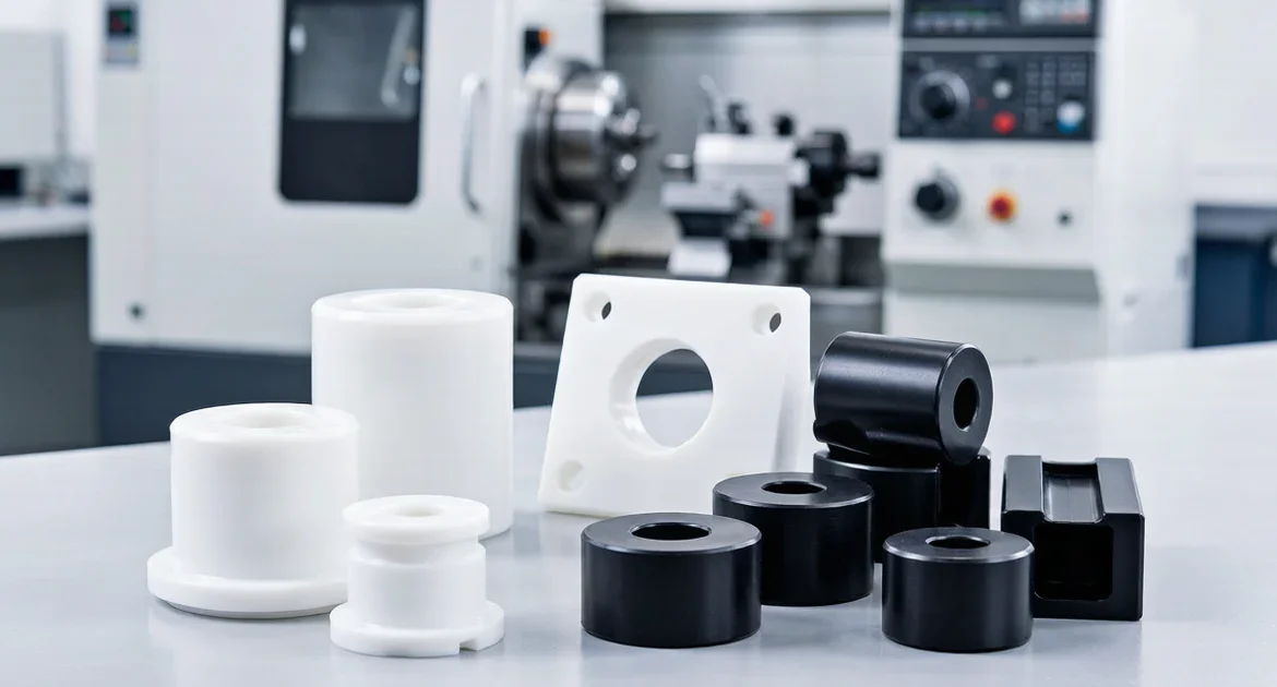
Turning is the most common operation for engineering plastic parts. Any component that is fundamentally round \u2014 a bushing, roller, sleeve, spacer, or ring \u2014 starts on the lathe. The key to quality in plastic turning is managing heat buildup while holding tight diameters.
Parts produced through turning:
- Bushings and sleeves — Cylindrical wear components with controlled inner and outer diameters. Often require bearing-fit tolerances on the ID and a slip-fit OD for housing installation.
- Rollers and guide wheels — Rotating components with bearing seats, shoulder faces, and sometimes crowned or grooved outer profiles. Concentricity between the bore and outer diameter is the critical dimension.
- Spacers and collars — Simple rings and spacing elements with parallel faces and controlled overall length. Face parallelism matters because these parts set axial position in an assembly.
- Rings and custom round parts — Application-specific turned components with shoulders, steps, grooves, or chamfers.
At GRAN, plastic turning uses sharp-positive rake tooling to shear rather than push the material. Coolant is used sparingly or not at all for materials like POM and nylon that absorb moisture, since dimensional stability can shift after a coolant-soaked part dries. Feed rates and spindle speeds are tuned to each plastic grade \u2014 a glass-filled nylon part turning at the speed of unfilled POM will produce a rough, torn surface.
2. Milling: Creating Profiles, Pockets, and Flat Surfaces
Milling handles the plastic parts that are not round: blocks, plates, insulators, guide rails, and adapter components with flat datum surfaces, pocketed features, slots, and profile outlines.
Parts produced through milling:
- Insulator plates and blocks — Flat components with mounting hole patterns, routed profiles, and pocketed features. Dimensional stability is the priority because these parts interface with electrical or structural assemblies.
- Guide rails and wear pads — Linear sliding elements with flat contact surfaces, mounting slots, and countersunk fastener holes. Surface quality on the sliding face determines friction behaviour in service.
- Adapter plates and covers — Custom-shaped plastic panels with outline routing, hole drilling, and edge profiling for OEM machine assemblies.
- Custom machined housings — Box-like or enclosure-style parts requiring multi-sided milling with pocket floors, internal corners, and threaded insert locations.
The main challenge in plastic milling is workholding without distortion. A plate clamped rigidly at the corners can bow upward in the centre, causing the pocket floor to be uneven. GRAN uses vacuum fixturing, low-profile clamping with distributed contact pads, and double-sided tape workholding for thin plastic sheets to keep the part flat without introducing stress.
3. Drilling, Boring, and Threading: Creating Functional Interfaces
Hole-making operations on engineering plastics carry their own set of risks. A drill that enters too aggressively can melt the hole wall rather than cut it. A bore that generates too much heat can close up after cooling. A tapped hole in plastic behaves very differently from the same thread in metal.
Hole-making operations at GRAN:
- Drilling — Through-holes for fasteners, clearance holes, and mounting points. Sharp drill geometry with high helix angles clears chips effectively and reduces friction in the hole. Peck drilling cycles break chips and prevent heat buildup in deep holes.
- Скучно — Precision internal diameters for bearing seats, bushing housings, and locating bores. Single-point boring tools allow diameter adjustment to compensate for material spring-back after the roughing pass.
- Threading — Threaded holes for fasteners and assembly features. For plastics, thread-forming taps can produce stronger threads than thread-cutting taps because they displace rather than sever the material, compressing the plastic around the thread profile. Thread inserts (helical or key-locking) are used when the joint will be assembled and disassembled repeatedly.
4. Surface and Edge Handling: Finishing for Fit and Durability
An engineering plastic part is not finished when the last cut is made. Surface and edge handling transforms a machined blank into an assembly-ready component with clean fits, smooth contact surfaces, and consistent batch appearance.
Post-machining handling includes:
- Deburring — Removing the flexible, stringy burrs that form on plastic edges. Manual deburring with a sharp blade at the correct angle works better than rotary deburring tools, which can melt or smear the plastic rather than cleanly removing the burr.
- Edge refinement — Breaking sharp corners with a controlled chamfer or radius. Plastic edges that feel sharp to the touch are often a sign of incomplete processing — a small 0.2 mm to 0.5 mm edge break improves handling safety and assembly feel without affecting functional geometry.
- Seat clean-up — Verifying that bearing seats, shoulder faces, and contact surfaces are free of burrs, chips, and cutting-fluid residue. A single trapped chip in a bearing seat can misalign a bearing by more than the tolerance band allows.
- Surface trimming — Light final passes on friction surfaces and visual faces to ensure consistent texture and appearance across the batch.
Which Process for Which Part: A Quick Reference
| Part Category | Поворот | Фрезерование | Drill/Bore | Edge/Surface |
|---|---|---|---|---|
| Bushings & sleeves | \u2713 | \u2713 | \u2713 | |
| Rollers & guide wheels | \u2713 | \u2713 | \u2713 | |
| Spacers & collars | \u2713 | \u2713 | ||
| Insulator plates | \u2713 | \u2713 | \u2713 | |
| Guide rails & wear pads | \u2713 | \u2713 | \u2713 | |
| Adapter plates & covers | \u2713 | \u2713 | \u2713 | |
| Custom housings | \u2713 | \u2713 | \u2713 |
How GRAN Reviews Engineering Plastic Projects Before Production
Every engineering plastic project goes through a structured review before machining begins. This process catches the issues that are expensive to fix after the first batch is cut.
- Geometry and service condition review — We examine the part outline, wall thickness, and the operating environment. A bushing that runs dry at elevated temperature needs different machining parameters than one that operates in an oil bath at room temperature. Thin-walled sections, tall unsupported features, and deep pockets are flagged for fixturing review.
- Feature and tolerance check — Bearing seats, mounting holes, thread specifications, and slip-fit or press-fit interfaces are checked against the drawing. Tolerances that are achievable in metal may need adjustment for plastic due to thermal expansion and moisture absorption properties.
- Processing route selection — Based on geometry and features, we determine the operation sequence. A part that needs both turning and milling, for example, has its turned features completed first while the part is still a solid round blank, providing maximum rigidity for the critical diameters.
- Surface and edge expectation alignment — We confirm whether the part has friction surfaces (where finish directly affects function), cosmetic faces, or assembly-critical contact areas. This determines the edge refinement and surface handling standard.
- Sample validation — A small sample batch is machined and inspected for diameter accuracy, surface condition, burr control, and assembly fit before full production. For parts with tight bearing fits, samples are measured at stabilised room temperature to confirm final dimensions.
For the complete workflow from drawing to delivery, see our CNC machining process overview.
Start Your Engineering Plastic Machining Project
If your project involves plastic bushings, rollers, insulators, guide parts, spacers, or custom OEM plastic components, GRAN INDUSTRIES SDN. BHD. has the processing capability to go from sample validation to repeat production with consistent quality.
Send your drawing, reference sample, or project brief to info@gran.my or call +60 10-881 2868. Include part geometry, material preference, quantity requirements, and any special operating conditions your parts will face. Our team reviews every inquiry and returns a quotation with the recommended processing route and lead time.
Learn more on our Engineering Plastic Machining service page.
Часто задаваемые вопросы
Q: Which engineering plastics can GRAN machine?
A: We machine a broad range of engineering plastics including POM (acetal/Delrin), nylon (PA6, PA66, glass-filled variants), PTFE (Teflon), UHMWPE, PEEK, and other engineering-grade thermoplastics. The right material depends on the application: POM for low-friction wear parts, nylon for toughness and impact resistance, PTFE for chemical resistance and high-temperature sliding, and PEEK for high-strength, high-temperature applications. If you are unsure which material fits your part, share the operating conditions during quotation and we will recommend the right grade.
Q: What tolerances can you hold on plastic turned parts?
A: Typical tolerances for turned plastic parts are \u00b10.05 mm on diameters and \u00b10.1 mm on lengths, but this depends on the material and part geometry. Tighter tolerances are achievable with stabilised machining conditions, but all plastic tolerances must account for thermal expansion and, in the case of nylons, moisture absorption. A nylon bushing machined to a tight bore tolerance on a dry day can measure differently after absorbing humidity. We discuss these material behaviours during quotation so you can specify tolerances that are both functional and realistic.
Q: Can you machine glass-filled or carbon-filled engineering plastics?
A: Yes, but filled plastics require different tooling and parameters compared to unfilled grades. Glass and carbon fibres are abrasive and wear standard carbide tooling faster. We use diamond-coated or specialised carbide tooling and adjust cutting parameters to manage tool life and surface finish on filled materials. The process is well-established \u2014 just let us know the material grade during quotation.
Q: What is the minimum order quantity for plastic CNC parts?
A: We support prototype and small-batch orders for initial design validation. Once the sample is approved, we move to production quantities based on your programme needs \u2014 no arbitrary minimum. Whether you need five parts for a fit-check or 5,000 for a scheduled OEM order, the project review and processing approach scales accordingly.
Q: Do plastic parts need different packaging or handling compared to metal parts?
A: Yes. Engineering plastics scratch more easily than metals, so individual part separation or compartmented packaging is used to prevent contact damage. Parts with tight bearing fits are packaged to keep them clean and free of debris, and nylon parts may be sealed in moisture-barrier packaging if dimensional stability during storage and transit is critical. We coordinate packaging based on your distribution requirements.