
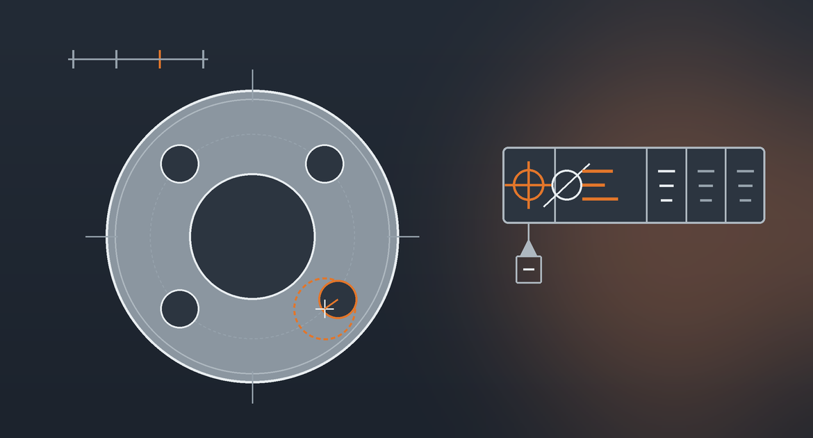
True position is the control that tells a supplier where a feature must actually end up. It appears on almost every drawing that has a bolt pattern, a dowelled interface, or a hole that must line up with something else — and it is the control most often left off, applied without a datum reference, or written in a way that means something different from what the designer intended.
This guide is for buyers and engineers preparing drawings for custom machined parts. It covers what a position callout needs in order to be reviewable before production, how position differs from the coordinate tolerances it replaces, and which decisions change the price of the part.
What True Position Actually Controls
Position controls the location of a feature’s axis or centre plane relative to defined datums. For a hole, it defines a cylindrical zone in which the hole’s axis must lie. The diameter of that zone is the tolerance value; the position of the zone is fixed by the basic dimensions and the datum reference frame.
The word “basic” matters. Dimensions that locate a positional zone are drawn boxed and carry no tolerance of their own — the position callout is the only thing toleranced. A drawing that boxes its locating dimensions and then also applies a general linear tolerance to them is contradictory, and it is one of the most common reasons a drawing goes back for clarification before quotation.
Position is not a substitute for size. The hole’s diameter still needs its own tolerance. Position says where the axis sits; the size tolerance says how big the hole is. Both are required, and they are checked separately.
Why a Round Zone Beats a Square One
Coordinate tolerancing — ±0.1 mm in X and ±0.1 mm in Y — produces a square tolerance zone. Position produces a round one. This is not a cosmetic difference, and it is worth understanding because it changes what you can ask for without adding cost.
A square zone of ±0.1 mm in each direction permits a diagonal error of about 0.141 mm at the corners, but only 0.1 mm along the axes. The part is allowed to be further out of position diagonally than orthogonally, which is rarely what the function requires. A round zone treats every direction the same.
Converting from coordinate to positional tolerancing on the same functional requirement usually yields a positional tolerance of roughly 1.4 times the coordinate value — ±0.1 mm in X and Y becomes a position tolerance of about ⌀0.28 mm. That is a genuine gain in permitted variation for identical assembly behaviour. On a bolt pattern where every hole is currently at ±0.1 mm, switching to position often removes cost without loosening the fit at all.
Always Reference Datums, in Order
A position callout without datum references is incomplete. The zone has to be located relative to something, and the drawing must say what that something is and in which order it applies.
The datum order is not arbitrary. The primary datum establishes orientation and takes the most contact; the secondary constrains rotation and translation in the next direction; the tertiary locks the remaining degree of freedom. Reversing the order changes how the part is held for machining and how it is set up for inspection, and it can change whether a part passes. Choose the order that reflects how the part is located in its assembly, not the order that is easiest to draw. Our guide on how to specify datum features and datum targets covers how to select those reference features in the first place.
Where a hole pattern must line up with a mating part, reference the same features that locate the two parts against each other in service. A pattern positioned to a machined face and two edges will behave differently in assembly from the same pattern positioned to a bore and a slot, even when the tolerance value is identical.
Material Condition Modifiers, and When They Save You Money
A position tolerance can be applied at regardless of feature size, or with a maximum material condition modifier. The difference has a direct effect on how many parts pass.
Applied at maximum material condition, the stated tolerance is the minimum available. As the hole is made larger than its smallest permitted size, the departure from maximum material condition is added to the position tolerance as bonus. A hole toleranced at ⌀0.2 mm position with an MMC modifier, drilled 0.05 mm above its minimum diameter, is permitted ⌀0.25 mm of position error.
That bonus is free tolerance for clearance holes, and it exists precisely because a larger clearance hole genuinely can tolerate more positional error and still assemble. For clearance holes, fastener holes and non-locating features, MMC is usually the correct choice and it will reduce your scrap rate.
Where the feature locates something — a dowel hole, a bearing bore, a press-fit seat — the bonus is not appropriate, because a larger hole does not help a part that must be held concentric. Those features should be toleranced regardless of feature size. See how to specify dowel pin features и how to specify press-fit features for the size and finish requirements that go with them.
Patterns, Composite Callouts and What They Cost
A group of holes toleranced as a pattern is controlled twice over: the location of the pattern as a whole relative to the datums, and the spacing of the holes relative to each other. These are different requirements and they frequently carry different values.
A composite position callout states both — a looser tolerance for locating the pattern on the part, and a tighter one for the relationship between holes within the pattern. This matches how most assemblies actually work. A bolt circle usually needs its holes tightly spaced relative to one another so the mating flange drops on, while the position of the whole circle on the face can move more.
Writing both requirements at the tight value is a common and expensive mistake. It forces the setup to hold the pattern’s absolute location to a tolerance the function never needed, and it can turn a single-setup job into a multi-setup one.
A Worked Example
Take a four-hole bolt pattern for M6 fasteners on a 50 mm bolt circle, in a bracket that mounts to a machined face.
Drawn conventionally, the holes might be ⌀6.6 +0.2/0 with each hole located at ±0.1 mm in X and Y. That reads as tight, and a supplier will quote it as tight. But the square zone it creates permits 0.141 mm of diagonal error, so the real functional requirement was never ±0.1 mm to begin with.
Written as position, the same functional requirement becomes: hole diameter ⌀6.6 +0.2/0, position ⌀0.28 mm at maximum material condition, referenced to the mounting face as primary and the locating bore as secondary. The bolt circle diameter and the angular spacing become basic dimensions.
Now consider what happens in production. A hole drilled at ⌀6.70 rather than the minimum ⌀6.60 has departed from maximum material condition by 0.10 mm, so the permitted position error becomes ⌀0.38 mm. A hole drilled near the top of its size band at ⌀6.78 is permitted ⌀0.46 mm. In every case the fastener still passes through and the bracket still mounts, because the extra clearance is what paid for the extra position error.
The functional outcome is identical to the coordinate version. The number of parts that pass first time is considerably higher, and nothing about the drawing has been loosened in a way that matters to the assembly.
What Position Costs to Hold
Position tolerance is one of the strongest cost drivers on a machined drawing, because it determines how many times the part must be picked up and how it is held.
Holes machined in a single setup on the same face hold position readily, because the machine’s own accuracy governs the result. As standard we work to ISO 2768-m for general dimensions, and hold ±0.005 mm on features that require it, across 88 CNC machines including 3-, 4- and 5-axis machining centres and turn-mill lathes.
The cost appears when positional relationships cross setups. A hole pattern on one face referenced to a bore machined from the opposite face has to survive a re-fixture, and the achievable position is then governed by fixturing repeatability rather than machine accuracy. Where that relationship is genuinely critical, a 4- or 5-axis setup that reaches both features without releasing the part is usually cheaper than a tight tolerance across two operations — a point covered further in когда использовать 5-осевую CNC-обработку.
Material behaviour matters too. A position tolerance that is routine in aluminium may need a different process in a work-hardening stainless, and in engineering plastics the part may move after machining by more than the tolerance itself. Tell us the material and the operating temperature alongside the tolerance, not after.
How Position Is Inspected
Position is measured against the datum reference frame, not against the edges of the part. The part is aligned to its datums first; only then does the measurement mean anything. This is why the datum order on the drawing changes the inspection result, and why a drawing that omits datums cannot be inspected consistently by two different suppliers.
For a functional gauge check, a fixed-limit gauge can verify a pattern at maximum material condition quickly and cheaply. For measured results, a CMM aligns to the datums and reports the deviation of each axis, from which the positional value is calculated. If you need the numbers rather than a pass or fail, ask for a dimensional report at quotation — it is straightforward to include, and awkward to add after the parts are cut. Our process page sets out what is checked on a first article and what can be supplied with the shipment.
Three Mistakes That Cost the Most
Toleranced basic dimensions. A boxed dimension with a general tolerance applied to it in the title block is a contradiction, and the supplier has to ask which one governs. It is the single most frequent query we raise on drawings carrying position callouts.
Position used where runout was meant. On turned parts, designers sometimes apply position to control how true a diameter runs relative to another diameter. Position controls the location of an axis; it does not control the form or the wobble of a surface as it rotates. For a shaft, a bearing journal or a sealing diameter, runout is the correct control — see how to specify runout.
The same tight value everywhere. Applying one position tolerance across every hole on a part, regardless of what each hole does, guarantees you pay for precision on features that never needed it. Separate the locating features from the clearance features and tolerance them differently. It is the cheapest change available on most drawings.
A Checklist Before You Release the Drawing
Before the drawing goes out for quotation, confirm the following. Each item removes a question that would otherwise come back to you.
- Locating dimensions are basic — boxed, and not also covered by a general linear tolerance.
- Every position callout carries a datum reference frame, with the datums in a deliberate order.
- Hole size tolerance is stated separately from position.
- Material condition modifiers are applied where they help: MMC on clearance holes, regardless of feature size on locating features.
- Pattern-to-datum and hole-to-hole requirements are separated where they genuinely differ.
- Any positional relationship that crosses two faces is marked, so the setup can be planned around it.
- Inspection expectation is stated — functional gauge, CMM report, or first article only.
Getting a Position Callout Quoted
A drawing that carries proper position callouts is faster to quote, not slower, because it removes the guesswork about which relationships matter. If you are unsure whether a tolerance is achievable in your chosen material, send the drawing and say which features are functional — we will tell you what is straightforward, what needs a particular setup, and what would be cheaper to change before anything is cut.
Related reading: how to specify precision holes, how to specify threaded holes, how to specify perpendicularity и how to specify profile tolerances. To discuss a drawing, свяжитесь с нашей инженерной командой.