How to Specify Internal Corners and Fillet Radii for CNC Machined Parts

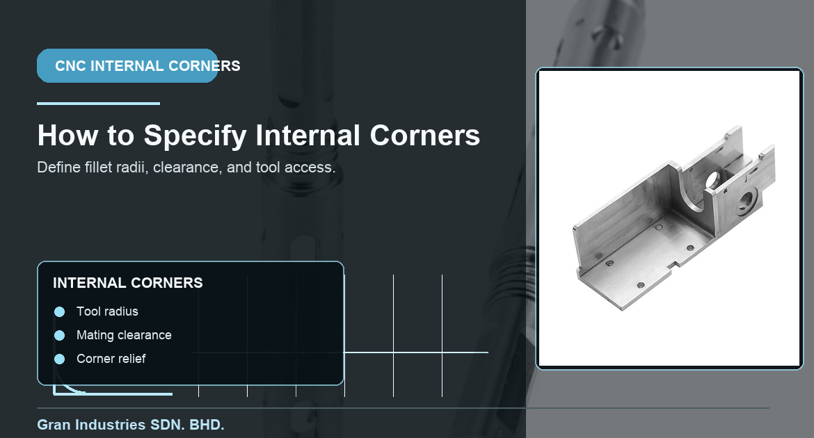
Internal corners are a frequent source of avoidable CNC machining cost and assembly trouble. A CAD model can show a perfectly sharp inside corner, but a rotating milling cutter has a round diameter and naturally leaves a radius. If a mating part, insert, seal, or electronics component needs to sit tightly into that corner, the drawing must show how the corner should function rather than assuming that a sharp virtual edge can be machined directly.

A practical internal-corner callout identifies the allowable radius, any clearance required by the mating part, the depth and access constraints of the surrounding feature, and the tolerance that actually matters. This lets the machining team select an efficient cutter and toolpath before production starts. It also prevents a late change when two otherwise correct components fail to seat together.

At Gran Industries, internal corners and fillets are reviewed with the complete feature geometry, material, tooling access, assembly condition, and inspection plan in mind. The objective is not to eliminate every radius. It is to make sure each radius is intentional and compatible with the part function.

Why a sharp internal corner is not a normal milling result

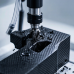
In CNC milling, an end mill removes material with a circular cutting profile. When the tool follows two perpendicular walls, it leaves an internal radius equal to the cutter radius unless a special process or relief feature is used. A model may display a sharp corner because CAD geometry has no tool diameter, but that corner is not directly reproduced by ordinary milling.

For most custom parts, specifying a practical internal radius is the simplest approach. It gives the shop freedom to choose a stable tool with reasonable reach and helps avoid extremely small cutters, repeated finishing passes, or unnecessary EDM work. A smaller radius can be made, but it usually requires a smaller and less rigid tool, which may increase time, deflection risk, or finish variation.

Start with the mating-part clearance requirement

The first question is not what radius a cutter can make. It is what the mating component needs. A square insert, a shoulder on another machined part, a PCB, a seal carrier, or a fastener feature may need clearance near the inside corner. If the mating component has its own radius or chamfer, the two parts may fit without a special detail. If it has a sharp outside corner, the receiving pocket may need a larger internal radius, a corner relief, or a different interface design.

Before quoting, clarify:

  • Whether another part must seat fully into the internal corner
  • Whether clearance is needed for an outside corner, radius, chamfer, or coating build-up
  • Which walls or pocket floors are functional contact surfaces
  • Whether the corner is cosmetic, clearance-only, load-bearing, sealing-related, or a datum feature
  • Whether an assembly drawing defines a required gap or contact condition

These details are more valuable than a vague note such as “sharp corner where possible.” They help the machining team make a feature that assembles as intended.

Choose the largest functional radius when possible

As a general manufacturing principle, use the largest internal radius that does not interfere with the part function. A larger radius permits a larger cutter, which is usually more rigid and can remove material more efficiently. It can also improve tool life and make the result more consistent across a production run.

This is not a fixed rule that applies to every feature. A radius must still match the mating geometry, wall thickness, material, finish requirement, and tolerance. But where the assembly allows it, avoiding an unnecessarily small internal radius can reduce the complexity of the milling process without changing how the part works.

Use corner reliefs when a mating component needs square clearance

A corner relief is a deliberate clearance feature added near an internal corner. It allows a square or near-square mating feature to seat while leaving the main walls and floor manufactured with practical milling tools. The relief may be circular, dog-bone shaped, T-bone shaped, or another geometry selected to match the assembly and manufacturing method.

The right relief depends on which directions the mating part must move during assembly and which surfaces actually locate it. A relief that works for a part inserted from above may not be appropriate for a part that slides sideways into position. The drawing should make the intended clearance and contact surfaces clear so the feature is not added mechanically without considering assembly behavior.

When the pocket also has a controlled depth or floor condition, review it together with Gran’s guide to ポケットの深さおよび床の状態. Corner relief alone does not resolve an unclear floor, wall, or seating requirement.

Tool reach and pocket depth affect achievable corner radii

Corner radius is linked to more than the nominal cutter diameter. In a deep pocket, the tool must reach the bottom while remaining sufficiently rigid. A long, small-diameter cutter can be more prone to deflection, vibration, heat, or slower cutting conditions. This may affect wall straightness, floor finish, and the practical cost of producing a tight internal corner.

For deep or narrow cavities, include the relevant depth, wall height, bottom condition, material, and finish requirement in the RFQ. The machining team can then evaluate cutter reach, chip evacuation, support for thin walls, and whether a relief, larger radius, alternate setup, or different process route is appropriate.

Internal fillets can improve part performance as well as manufacturability

Not every internal radius is only a manufacturing concession. Fillets can reduce stress concentration in loaded corners, improve material flow around a transition, and remove a fragile sharp edge from the design. The appropriate radius depends on loading, material, wall thickness, mating constraints, and the specific application; a CNC shop should not infer engineering intent that is absent from the drawing.

When the corner is structurally important, specify the radius as an engineering requirement and identify the surfaces or transition it applies to. When the radius is only for machining access, communicate the allowable limit instead. This distinction helps preserve the right design intent while keeping the manufacturing route practical.

Define tolerances only where the corner function requires them

An internal radius does not always need a separate tight tolerance. If the radius only clears a non-critical area, an overly restrictive value can force the use of a small finishing tool and extra inspection without improving the assembled product. If the radius controls a seal, load path, mating feature, or other functional interface, then a clearer and more specific callout may be justified.

The same reasoning applies to the position and shape of the surrounding pocket or wall. A correct radius cannot compensate for a wall that is in the wrong location, a floor that is too deep, or a datum relationship that does not represent the assembly. Use a coherent datum strategy, as discussed in Gran’s article on 基準点の特徴と基準点ターゲット, before tightening local details independently.

Material and finish requirements change the process details

Aluminum, stainless steel, copper alloy, engineering plastics, and carbon-fiber composites can all require different cutter geometry, engagement, support, and finishing strategy. A small internal radius in a thin aluminum wall may have a different machining risk than the same feature in a rigid steel block. Coating, anodizing, bead blasting, or deburring can also influence how a corner fits and feels after machining.

For features where finish or contact quality matters, state that requirement separately from the radius. Gran’s guide to surface finish before quotation and production explains why visual and functional finish requirements should not be left as an implied consequence of a nominal geometry.

Inspection should reflect the actual corner requirement

Inspection should confirm the function shown on the drawing. A radius gauge, CMM program, optical method, pin, or functional mating check may be appropriate depending on the size and criticality of the feature. If the real requirement is clearance for another part, a functional gauge or assembly check may provide more useful evidence than measuring an isolated radius alone.

For production-critical geometry, state whether the radius, pocket clearance, or surrounding feature belongs in first article inspection or final acceptance. This avoids disagreement over whether the shop is verifying the CAD shape, the specified radius, or the actual fit condition.

Frequently asked questions about internal corners for CNC parts

Can CNC milling make a perfectly sharp internal corner?

Ordinary milling leaves a radius because the cutter is round. A special process such as EDM may be considered for certain parts, but it should be selected because the function requires it, not because a CAD model shows a sharp edge by default.

What internal corner radius should I use?

Use the largest radius that still supports the mating and functional requirement. The practical value depends on pocket depth, access, material, wall stiffness, tolerance, and the required assembly clearance.

When should I use a dog-bone corner relief?

Use a corner relief when a mating feature needs square clearance but the main pocket should remain economical to mill. The relief geometry should match the insertion direction and the surfaces that locate the mating part.

Do larger corner radii reduce CNC machining cost?

They often can, because they allow larger and more rigid cutters. The actual effect depends on the complete part geometry, material, quantity, finish, and tolerance requirements.

Make internal corners intentional before quotation

A clear internal-corner specification tells the CNC machining team what must fit, which surfaces matter, and where the design allows manufacturing freedom. Use practical radii where possible, add relief only when assembly needs it, and identify functional tolerances rather than tightening every corner by default.

For custom parts with deep pockets, tight mating interfaces, thin walls, or critical internal fillets, おばあちゃんに、あなたの絵とプロジェクトの詳細を送ってあげてください. We can review the corner geometry before quotation and help identify a manufacturable approach that preserves the intended function.

お買い物カゴに商品がありません。