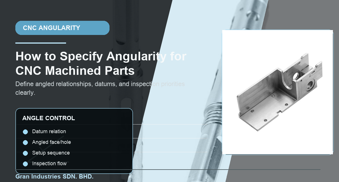
Angularity is a useful geometric control when a CNC machined part depends on a specific orientation that is neither parallel nor perpendicular to a datum. An angled face may guide flow, seat a mating component, provide clearance, or position a fastener interface. A hole may need to enter at a controlled angle relative to a mounting surface. A chamfered or tapered contact area may depend on more than one local dimension to function correctly. When that intent is not described clearly, the supplier may quote the feature as ordinary geometry instead of as a true orientation requirement.
The difficulty is that angularity can look simple on a drawing while carrying a larger setup and inspection burden than expected. A nominal angle alone may not fully communicate which datum matters, how the part should be held, or whether the orientation affects assembly, sealing, movement, or appearance. If that context is missing, the machining plan may prioritize the wrong reference and the measured result may not match the real functional need.
At Gran Industries, angularity is reviewed as a practical orientation control tied to how the part is made and used. The goal is to make sure the drawing identifies the correct datum relationship, the actual risk behind the angle, and the inspection expectation before machining begins.
Start by identifying which feature needs controlled angle orientation
Angularity only becomes meaningful when the controlled feature and the datum reference are both clear. One part may need an angled face relative to a base plane. Another may need a drilled axis held at a specific angle to a bore. A third may depend on an inclined shoulder or seating surface that positions a mating part during assembly. Those are not interchangeable cases even though the same geometric symbol may appear on the drawing.
Useful first questions include:
- Which feature is being controlled: a face, axis, hole, shoulder, or contour?
- Which datum reflects the part’s real setup or assembly reference?
- Does the angle affect fit, flow, contact, clearance, sealing, or appearance?
- Will the feature be machined and inspected from the same datum logic?
- Is the angle function-critical or only generally desirable?
When those answers are explicit, the angularity callout becomes a manufacturing instruction instead of a visual preference.
Angularity should be tied to a datum, not only to a nominal angle
A print can show a numerical angle and still leave the real manufacturing requirement unclear. The reason is that angularity is about orientation relative to a datum, not just about reaching a target number in space. If the datum is poorly chosen or implied rather than defined, the feature may be machined at the correct nominal angle but from the wrong reference, which can still cause assembly or inspection failure.
This is why angularity overlaps closely with datum features and datum targets. A broad face may be the correct datum in one part, while another part may need a bore axis, seating pad, or local support condition to represent actual use correctly.
Before quotation, it helps to confirm:
- Which feature is the primary datum
- Whether the angle is controlled to a plane or an axis
- Whether local datum targets are needed for realistic support
- How the part will be re-established if multiple setups are required
Angled faces, holes, and contact surfaces do not create the same machining problem
One angled feature may be easy to machine and difficult to inspect, while another may be easy to inspect and difficult to fixture. An angled flat can often be machined with a controlled setup, but an angled bore or hole may depend more heavily on drilling path, local stiffness, and datum strategy. A contact surface may care less about the visible angle itself and more about where that surface lands relative to other functional geometry.
That is why angularity planning often connects to Präzisionslöcher, profile tolerances, und locator faces. The same nominal angle may mean very different things depending on the feature type.
Do not tighten angularity more than function requires
It is tempting to add a very small angularity tolerance because the controlled feature looks important. But tighter orientation control usually means stricter fixturing, more careful stock allowance, more detailed inspection, and sometimes a slower machining sequence. If the feature does not drive a real assembly or performance risk, that added control may increase cost without improving the part in practice.
Dies folgt der gleichen Logik, die in tight tolerances, cost, and lead time. Stronger control is worth it when it protects the real function of the part. It becomes wasteful when it is used as a default on any feature that happens to be angled.
A practical review should ask:
- What would fail if the angle drifted more than the specified amount?
- Is the feature critical during assembly, operation, or both?
- Does prototype work need the same control as repeat production?
- Would a different datum or feature strategy communicate the need more clearly?
Surface finish and edge condition may change how an angled feature behaves
An angled face may meet its orientation tolerance on paper and still behave poorly if the contact surface is rough, burred, or damaged at the edge. A tapered or inclined contact face may seat differently if the edge rolls over or if the finish changes how the mating part contacts the surface. An angled drilled hole may also need cleaner edge control so hardware or fluid paths perform as expected.
That is why angularity often needs to stay connected to surface finish und Anforderungen an Kantenbruch und Entgratung. The supplier should know whether the angle itself is enough, or whether the contact quality around that same feature matters just as much.
Material behavior and setup stability affect angular results
Angularity is not only a programming problem. Thin sections, long reaches, angled drilling paths, and stress-sensitive materials can all influence how closely a feature holds the intended orientation after machining and unclamping. Aluminum may shift differently from stainless steel. Engineering plastics may deflect under cutting pressure. Carbon fiber and mixed-geometry parts may need local support or alternate tool strategy to maintain consistent angle control.
That is why angularity should be reviewed together with part stiffness and material family. Components in CNC-Bearbeitung von Aluminiumlegierungen, CNC-Bearbeitung von Edelstahl, Bearbeitung von technischen Kunststoffen, oder Kohlefaserverarbeitung may all need different setup and inspection strategies even when the print symbol looks similar.
Inspection should reflect the same orientation logic as the print
Angularity results only make sense when the inspection setup reflects the same datum logic and contact condition shown on the drawing. If the part is checked from a different face, axis, or unstable support scheme, the reported result may not describe how the feature behaves in the real assembly. This matters most when the angled feature interacts with holes, contact surfaces, sealing interfaces, or locator geometry downstream.
An authoritative external reference for the broader GD&T rules is the ASME Y14.5 standard, which defines the framework used for orientation controls such as angularity. In production practice, the important part is still making sure the inspection setup mirrors the datum intent on the print.
Helpful inspection questions include:
- Which datum simulator or datum setup will be used?
- Is the controlled feature a face, line, axis, or angled hole?
- Sollte die Funktion in die Liste aufgenommen werden? Erstmusterprüfung?
- Does the measurement setup reflect how the part will actually seat or align in use?
What to include in an RFQ when angularity matters
If your part depends on angularity for function or assembly, the RFQ is stronger when it includes:
- 2D-Zeichnung und 3D-Modell, sofern verfügbar
- Clear identification of the controlled feature and its datum reference
- Notes describing whether the angle affects fit, contact, flow, sealing, or clearance
- Any related finish, edge, or contact-surface expectations
- Inspection priorities for prototype or production acceptance
- Material and quantity context so the supplier can quote the real process
That package helps the supplier price the angled feature as a functional orientation requirement rather than as a simple geometric detail.
Clear angularity callouts reduce avoidable setup and fit problems
Angularity is most useful when a CNC machined part depends on a controlled non-square orientation between critical features and their datums. When the drawing clearly shows which feature is controlled, what datum matters, and how the feature will be checked, the machining team can plan the process with fewer assumptions and the finished part is more likely to behave correctly in assembly.
If your custom CNC machined part includes angled faces, angled holes, tapered contact surfaces, or datum-controlled orientation features, Gran Industries can review the drawing and machining approach before quotation. You can also Senden Sie Ihre Projektdetails zur Überprüfung wenn Sie bereit sind.