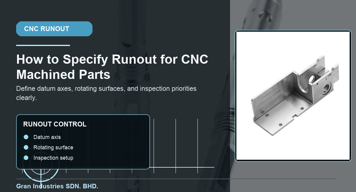
La excentricidad es un parámetro de control útil cuando una pieza mecanizada con CNC presenta un elemento giratorio, de posicionamiento o de sellado que debe mantenerse en una relación constante con un eje de referencia. Entre los ejemplos más comunes se encuentran los ejes, los muñones de cojinetes, los diámetros de sellado, las bridas de montaje y las caras torneadas. Un plano puede indicar los diámetros nominales correctos y, aun así, dejar poco clara la relación funcional entre esas superficies. Cuando eso ocurre, una pieza puede parecer correcta en una simple comprobación del diámetro, pero ofrecer un rendimiento deficiente en rotación o durante el montaje.
Un requisito claro de excentricidad ayuda a los equipos de mecanizado e inspección a comprender qué elementos deben permanecer estables cuando la pieza se referencia a su eje funcional. Además, evita que un proveedor dé por sentado que todas las características que parecen concéntricas requieren el mismo nivel de control. El objetivo práctico no es añadir más GD&T por defecto, sino comunicar la relación que realmente protege la funcionalidad.
En Gran Industries, el descentramiento se analiza teniendo en cuenta la estrategia de referencia de la pieza, la secuencia de torneado o fresado, el comportamiento del material y el método de inspección. Ese análisis previo hace que la elaboración de presupuestos y la planificación del proceso sean más fiables, tanto para prototipos como para la producción en serie.
Empieza por la función de la pieza, no por el símbolo
Antes de añadir una nota sobre la excentricidad, hay que determinar qué función debe cumplir la pieza. Es posible que un muñón de cojinete necesite una rotación estable con respecto al eje de un eje. Es posible que el diámetro de una junta requiera un movimiento controlado para reducir el contacto desigual. Es posible que la superficie de una brida deba evitar la oscilación al fijarse a un conjunto de acoplamiento. Se trata de problemas funcionales distintos, incluso cuando toda la geometría se encuentra en una sola pieza torneada.
Algunas preguntas iniciales útiles son:
- ¿Qué superficie o elemento gira, se acopla, sella o fija otra pieza?
- ¿Qué eje sirve de referencia funcional durante el montaje?
- ¿Se aplica este requisito a un elemento circular, a toda la superficie o a una cara?
- ¿Qué fallo se produciría si la característica variara más allá del límite propuesto?
- ¿Se inspeccionará la pieza con la misma orientación con la que funciona?
Responder a esas preguntas permite que la nota sobre la desviación esté vinculada a una necesidad concreta de montaje, en lugar de utilizarla como una indicación general de precisión.
Elige un eje de referencia que se ajuste a la orientación de la pieza.
La excentricidad se evalúa en relación con un eje de referencia. Esto significa que la característica de referencia debe representar la superficie, el orificio o la línea central que realmente sitúa a la pieza en su posición de uso. El diámetro de un eje puede ser una característica de referencia lógica para un componente, mientras que un orificio de precisión es la mejor referencia para un cubo o un manguito. Si se utiliza una referencia incorrecta, la inspección puede arrojar un valor que, aunque técnicamente repetible, no guarde relación con el ensamblaje real.
Por eso, la planificación de la salida comienza con la misma lógica de referencia que se explica en la guía de Gran sobre características de referencia y puntos de referencia. El plano debe dejar claro qué elemento define el eje, cómo se sujeta dicho elemento durante la inspección y qué superficies deben mantenerse alineadas con él.
Utiliza el control adecuado para la función que deseas proteger
La excentricidad no es intercambiable con todos los controles geométricos relacionados. Una tolerancia de diámetro controla el tamaño. Un requisito de rectitud puede controlar la forma de un elemento del eje. La perpendicularidad puede controlar la orientación de una cara respecto a un eje. El perfil puede controlar una superficie más compleja. La excentricidad es adecuada cuando lo que importa desde el punto de vista funcional es la relación de una superficie con un eje de referencia durante la rotación.
Por ejemplo, el diámetro de una junta puede estar dentro de los límites de tamaño y, aun así, variar con respecto al eje de rotación. Una superficie de montaje puede ser perpendicular en una comprobación simplificada, pero requerir una evaluación basada en la rotación debido a su forma de acoplamiento. Por el contrario, es posible que un elemento no giratorio no necesite ninguna tolerancia de excentricidad. La clave está en utilizar el criterio de control que describa el riesgo real, no el que parezca más restrictivo.
Para conocer el contexto más amplio que subyace a esta decisión, el Norma ASME Y14.5 es la referencia de referencia en materia de dimensionamiento y tolerancias. En una solicitud de presupuesto, una breve nota en la que se explique la función del conjunto suele ser tan útil como el propio símbolo.
Indica claramente la superficie controlada
Indica con exactitud a qué se aplica el requisito de excentricidad. En un elemento cilíndrico, identifica el diámetro o la superficie específicos. En una cara, deja claro que esta se controla en relación con el eje de referencia. En un eje escalonado, no des por sentado que una sola referencia describe automáticamente todos los diámetros, rebordes o ranuras. Cada elemento debe evaluarse según su función en el ensamblaje.
Este nivel de claridad es importante cuando una pieza combina elementos torneados y fresados. Una brida mecanizada, una sección roscada, un orificio de precisión o una superficie de montaje pueden requerir cada uno una relación diferente con respecto al eje principal. Detalles relacionados como, por ejemplo, agujeros de precisión y hombros y caras de referencia deben seguir siendo comprensibles como requisitos funcionales propios.
Ten en cuenta la secuencia de montaje antes de ajustar la tolerancia.
Un valor de excentricidad reducido puede influir en la secuencia de operaciones de torneado, fresado, sujeción e inspección que sigue un taller. Cuando los diámetros críticos pueden acabarse en una misma configuración a partir del mismo punto de referencia, mantener su relación suele ser más sencillo. Si la pieza debe retirarse, darse la vuelta, someterse a un tratamiento térmico, recubrirse o mecanizarse en varias operaciones, el proceso puede requerir una recuperación adicional del punto de referencia, un margen de material o pasos de inspección adicionales.
El material y la geometría también son importantes. Los ejes largos y delgados pueden deformarse. Las bridas finas pueden moverse al sujetarlas. Los conjuntos de aluminio, acero inoxidable, plásticos técnicos y fibra de carbono responden de forma diferente a las fuerzas de apoyo y de corte. El control adecuado debe tener en cuenta la rigidez de la pieza y el proceso de producción, en lugar de copiar un valor de un plano que no tenga relación con el caso.
Esa es la misma relación entre coste y riesgo que se aborda en el artículo de Gran sobre tolerancias estrictas, coste y plazo de entrega. Se justifica un valor más ajustado cuando protege la vida útil de los rodamientos, las juntas, las vibraciones o la alineación del montaje. Sin embargo, supone un trabajo innecesario cuando la función no depende de ello.
Planifica la inspección en torno al mismo eje de referencia
La inspección de excentricidad solo tiene sentido cuando la pieza se sitúa con respecto a la característica de referencia identificada en el plano. Dependiendo de la pieza, esto puede implicar el uso de centros, un dispositivo de sujeción de precisión, un simulador de agujero, un husillo u otra referencia controlada. El indicador, el programa de la máquina de medición por coordenadas (CMM) o el calibre de producción deben evaluar la superficie utilizando la misma lógica de referencia que prevé el diseño.
Antes de iniciar la producción, hay que ponerse de acuerdo sobre:
- La característica de referencia y cómo se simulará
- La superficie, el diámetro o la cara que se está comprobando
- Tanto si la necesidad se evalúa en un lugar concreto como si se hace en toda la superficie funcional
- Si la pieza requiere documentación del primer artículo, controles durante el proceso o registros de inspección final
- Cualquier condición que, tras el acabado, el recubrimiento, el montaje o el tratamiento térmico, afecte a la aceptación
Cuando la característica sea fundamental, inclúyela en el inspección del primer artículo plan. Esto suele ser más útil que detectar una discrepancia en los datos o en las mediciones una vez finalizado un lote.
Qué incluir en una solicitud de presupuesto cuando el descentramiento es un factor importante
Una solicitud de presupuesto (RFQ) más detallada proporciona al proveedor el contexto suficiente para ofrecer un presupuesto que se ajuste a las necesidades reales. Incluya el plano en 2D y el modelo en 3D cuando estén disponibles, identifique el eje de referencia, marque las características controladas y explique si la cuestión se refiere al ajuste del rodamiento, al sellado, a la rotación, al asentamiento de la brida o a cualquier otra función de montaje. Añada los requisitos relativos al material, la cantidad y el acabado superficial, así como cualquier documentación de inspección que se exija para la aceptación del prototipo o de la producción.
También resulta útil señalar cualquier pieza de acoplamiento o condición de montaje que haga que la relación sea crítica. Cuanto más claramente se definan el eje funcional y el método de aceptación, menos probable será que el presupuesto se base en suposiciones.
Las indicaciones claras sobre el descentramiento garantizan la fiabilidad de las piezas a medida
La excentricidad resulta más eficaz cuando controla una superficie funcional específica con respecto al eje de referencia que utiliza la pieza en el montaje. Con un punto de referencia claro, una indicación precisa, una tolerancia realista y un plan de inspección adecuado, los equipos de mecanizado CNC pueden optar por un proceso estable y verificar el resultado con confianza.
Gran Industries puede revisar los planos en lo que respecta a elementos giratorios, de posicionamiento, de estanqueidad y mecanizados de precisión antes de elaborar el presupuesto. Para un nuevo proyecto de piezas a medida, Envía el plano y los detalles del proyecto a Gran para recibir comentarios sobre la fabricación.