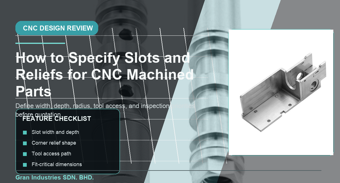
Slots and reliefs are common features in CNC machined parts, but they are also easy to underspecify. A drawing may show a narrow slot, a tool-clearance notch, a corner relief, or a long channel without explaining which dimensions actually matter in assembly or function. When that happens, the machining supplier has to interpret tool access, corner shape, tolerance priority, and inspection needs before quotation is even complete.
These features often look simple in a CAD model because they are only voids in the material. In production, however, slots and reliefs affect cutter selection, machining time, setup stability, corner radius limits, and how the part is checked. A small change in width, depth, or internal corner condition can make a significant difference to manufacturability.
At Gran Industries, slot and relief review is part of the broader drawing-review process for custom CNC machined parts. The practical goal is to separate functional requirements from geometric assumptions so quotation, machining, and inspection can stay aligned from the beginning.
Start with the function of the slot or relief
Not every slot serves the same purpose. One slot may provide clearance for a mating tab, another may allow tool entry, another may create a clamping path, and another may reduce weight or allow movement. Reliefs can also serve different roles, such as clearing an internal corner, supporting assembly fit, reducing stress concentration in a local area, or giving a cutting tool enough space to complete another feature cleanly.
Before quoting or machining begins, it helps to answer a few basic questions:
- Does the slot locate another component or only provide clearance?
- Is the relief needed for tool runout, corner clearance, or assembly fit?
- Which dimensions are critical: width, depth, position, corner radius, or surface condition?
- Does the feature interact with a hole pattern, thread, pocket, or datum face?
- Is the requirement the same for prototype and repeat production?
When the feature function is clear, the machining team can focus on what needs control instead of assuming that every visible dimension is equally important.
Why slot and relief details affect CNC machining quotes
Slots and reliefs can influence tool diameter, tool reach, cycle time, setup planning, and inspection effort. A narrow slot may require a smaller tool and slower machining. A deep relief may need extra passes or a longer cutter. A tight internal corner may not be feasible with standard tool geometry. If the drawing leaves these details ambiguous, the quote may not reflect the real process needed to make the part consistently.
This is why slot and relief geometry should be reviewed during examen des dessins avant l'établissement des devis d'usinage CNC et la production. Without that review, the supplier may need to build conservative assumptions into the quotation or come back with clarification requests after the RFQ is already in progress.
Closer review is usually warranted when the part includes:
- Narrow slots with limited tool access
- Deep channels or grooves relative to slot width
- Reliefs at internal corners that interact with mating parts
- Slots near thin walls, holes, or threaded features
- Features that must align to datum-controlled surfaces
- Long slots where straightness or wall finish affects assembly
Width, depth, and length should not be treated in isolation
Slot dimensions are connected. A width that looks acceptable on its own may become difficult when paired with a deep reach, a long unsupported run, or a strict positional requirement. Relief geometry can behave the same way. A notch or corner cut may be easy to machine at one depth and far more difficult at another if the cutter needs to reach past other walls or avoid nearby features.
A useful RFQ should clarify not only the nominal size of the feature, but how that size relates to the surrounding geometry. Helpful points include:
- Minimum slot width
- Required slot depth and whether the floor is function-critical
- Feature length and end condition
- Whether the slot walls or the slot centerline matter most
- Whether a relief is local or runs through the feature path
This keeps the drawing focused on functional control instead of leaving the manufacturing team to reverse-engineer the design intent from nominal geometry alone.
Internal corner radius and relief shape matter
Many slot and relief issues start at internal corners. CNC tools are round, so internal corners will usually have a radius unless another process is specified. If a mating component expects a sharp corner but the drawing does not allow a realistic internal radius or corner relief, assembly problems can appear later even if the part looks close to nominal dimensions.
For this reason, drawings should identify whether the feature needs:
- A standard internal radius that matches tool capability
- A defined corner relief for assembly clearance
- A local notch or dog-bone style clearance to fit a square mating feature
- A cosmetic corner condition versus a functional assembly condition
- A controlled edge-break or deburring limit at the slot entrance
If a square internal corner is not actually required, allowing a practical radius may improve machining stability and reduce cost. If corner clearance really matters, the drawing should state that explicitly instead of relying on an idealized model.
Slots near holes, threads, or thin walls need extra review
Slots and reliefs often interact with other critical features. A slot may cross a pattern of trous de précision, sit beside a threaded hole, or reduce stiffness near a mounting face. A relief may remove material near a thin wall and make the part more sensitive during clamping or finishing. In these cases, the feature cannot be reviewed alone.
Useful review questions include:
- Does the slot weaken a local wall or support surface?
- Does the relief change how a threaded feature is machined or inspected?
- Does the feature sit inside a datum-controlled zone?
- Will the channel affect flatness, parallelism, or assembly contact?
- Should the slot be located by centerline, edge, or another datum relationship?
That kind of context helps prevent the feature from being treated as just an isolated cutout in the model.
Tolerances should match the real job the feature must do
Some slots need accurate width because they guide or locate another part. Others only need enough clearance for movement, cable routing, venting, or tool entry. Reliefs may simply remove interference, or they may control a very specific assembly condition. If every dimension is toleranced tightly by default, machining time and inspection effort can increase without improving the finished part.
Cela suit la même logique que celle exposée dans Comment les tolérances serrées affectent le coût et les délais d'usinage CNC. Precision is valuable when it protects function. It becomes inefficient when it is applied broadly because the drawing has not separated critical dimensions from general geometry.
A stronger specification usually identifies:
- Which slot widths are fit-critical
- Which depths are functional versus general machining dimensions
- Whether position to a datum matters more than local size
- Whether the relief controls assembly or only prevents interference
- Which dimensions should be part of first article inspection
Material and part stiffness can change the machining strategy
Slots and reliefs do not behave the same way across all materials. Aluminum may machine efficiently but can still move when long slots remove stiffness from a part. Stainless steel can demand more control around tool pressure and heat. Copper alloys, engineering plastics, and carbon fiber each introduce different considerations for edge condition, local stability, and support during machining.
That is why slot geometry should stay connected to material planning. Projects involving alliage d'aluminium Traitement CNC, usinage CNC de l'acier inoxydable, copper and copper-alloy machining, ingénierie de l'usinage des matières plastiques, ou traitement de la fibre de carbone should not assume the same toolpath and slot strategy will work equally well in every case.
Where the part includes long slots, narrow webs, or local reliefs near low-stiffness areas, it is also useful to consider the same planning logic used for thin-wall CNC machined parts.
Surface finish and edge condition can be part of the same requirement
Slots and reliefs are often located in areas where burr control, surface finish, or edge condition matters. A slot may guide another part and therefore need smoother sidewalls. A relief may be hidden and need only clean machining. A visible slot on an external face may need a better cosmetic edge condition than an internal clearance cut.
For that reason, the drawing should not separate geometry from finishing assumptions. If the feature has a functional surface finish requirement or a defined deburring limit, that note should be tied to the feature directly. This is closely related to surface finish planning et edge break and deburring requirements for CNC machined parts.
Inspection should focus on acceptance-critical dimensions
A slot or relief can be measured in different ways depending on what matters. Some parts need width and positional verification. Others need only a functional confirmation that the feature clears a mating condition. If the inspection requirement is not aligned with function, time may be spent checking non-critical dimensions while the real fit issue remains unclear.
Inspection planning should define:
- Which dimensions determine part acceptance
- Which datum setup should be used
- Whether slot width, location, or depth is the critical result
- Whether the relief is measured directly or validated by assembly fit
- Whether the feature needs attention during inspection du premier article
This helps keep inspection practical and connected to the reason the feature exists.
What to include in an RFQ when slots or reliefs matter
For custom CNC machined parts that rely on slots or reliefs, the quotation package is stronger when it includes:
- Dessin en 2D et modèle en 3D si disponible
- Clear slot width, depth, and location requirements
- Internal radius or corner-relief expectations
- Notes showing whether the feature is for fit, clearance, or tool access
- Material grade and expected quantity
- Related tolerance notes on nearby holes, threads, or datum faces
- Surface finish and deburring requirements for affected edges
- Inspection or first article expectations tied to the feature function
That information lets the supplier review the part as a manufacturing problem instead of just a geometric cavity inside the model.
Clear slot and relief requirements support better machining outcomes
Slots and reliefs may be secondary features in a drawing, but they often control fit, clearance, tooling access, local stiffness, and assembly reliability. When the feature purpose, dimensions, corner condition, and inspection priority are clear, the quote becomes more accurate and the machining plan becomes more stable.
If your custom CNC machined part includes slots, channels, corner reliefs, or local clearances, Gran Industries can review the drawing, material, tolerance approach, and production intent before quotation. You can also envoyez les détails de votre projet pour examen lorsque vous êtes prêt.