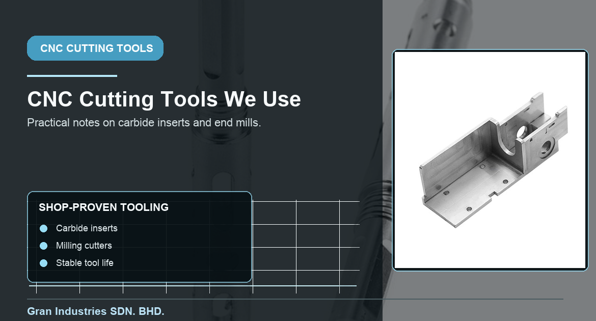
In CNC machining, the cutting tool is part of the process plan, not an afterthought. The same drawing can behave very differently depending on the insert geometry, end-mill style, coating, holder condition, tool reach, and cutting data used to make it. At Gran Industries, the tools we keep in regular use are the ones that have proven practical in our own machining work: they support stable cutting, give predictable wear behavior, and help us make repeatable decisions from prototype work through production runs.
This is not a claim that one insert or end mill is the best choice for every job. Material grade, machine rigidity, fixture support, coolant strategy, feature geometry, and required finish all change the answer. Instead, this article explains what we look for when selecting the CNC cutting tools used in our shop, and why that selection matters to custom-part buyers.
What we look for in CNC cutting tools
Our first priority is consistent, controllable machining. A tool that can make one good part but varies as it wears is rarely the right production choice. We look for cutting tools that give a stable process window for the actual material and geometry, then set up the job so the toolholder, reach, workholding, and inspection plan all support that choice.
In practice, we review:
- Material family and condition, such as aluminum, stainless steel, copper alloy, engineering plastic, or carbon-fiber composite
- Feature type: turned diameter, shoulder, bore, pocket, slot, threaded feature, face, or complex milled contour
- Tool access, overhang, wall stiffness, and whether the part needs more than one setup
- Surface-finish and edge-condition requirements
- Expected quantity and whether the job is a prototype, repeat order, or ongoing production part
- How tool condition will be monitored before part quality is affected
That approach keeps the focus on the finished component. The goal is not to use an impressive-looking tool. It is to select a tool that helps the machining process hold the dimensions, finish, and consistency the part actually needs.
Carbide inserts we use for turning work
For turning, carbide inserts are a practical choice because they let the process be matched to the feature and material. Insert shape, nose radius, chipbreaker, grade, and coating all influence how the cut behaves. A geometry that works well for a roughing pass on steel may be a poor fit for a thin-wall finish pass, a small internal bore, or a softer non-ferrous material.
The inserts we use regularly are selected for predictable chip control and a finish that remains stable over the intended tool-life window. On a shaft, bearing seat, or sealing diameter, that consistency matters because a gradual change in cutting behavior can affect both size and surface quality. For custom work, we also consider whether an insert can reach the feature without introducing unnecessary deflection or holder interference.
This is especially important when a turned feature is tied to fit or rotation. A suitable insert is only one part of the solution; datum strategy, setup sequence, and inspection still determine whether the result performs as designed. Related requirements such as bearing seats and bearing bores o runout should be reviewed as part of the complete process, not isolated from the cutting tool.
End mills we use for stable milling
For milling work, our end-mill selection starts with the material, the amount of radial and axial engagement, tool reach, and the feature’s finish requirement. A short, rigid tool with a suitable flute count often gives a more stable result than a longer tool pushed beyond its practical reach. Where access requires more reach, the process may need lighter engagement, different toolpath planning, or additional support for the part.
We use carbide end mills because they are well suited to the repeatable milling operations common in custom CNC parts, but the exact style is chosen for the work rather than by habit. Aluminum may benefit from a geometry that clears chips efficiently. Stainless steel may need a different balance of edge strength, heat management, and engagement. A narrow slot, deep pocket, thin wall, and finishing contour each put different demands on the tool.
For buyers, the useful point is that the programmed path and the tool are linked. A pocket with limited chip evacuation, for example, is not simply a question of nominal width and depth. The machining team must consider cutter access, chip removal, wall rigidity, and the finish expected on the floor and side walls. Gran’s guide to pocket depths and floor conditions explains why those drawing details should be clear before quotation.
Tool performance means more than cutting fast
Good cutting performance is not measured only by cycle time. In our own use, a tool earns its place in the process when it helps maintain a steady cut, manageable chip flow, reasonable tool life, and a finish that can be inspected consistently. A faster setting that causes unstable vibration, heat buildup, burr formation, or rapid variation near the end of tool life can create more work than it saves.
Tool wear is monitored because it is a normal part of machining, not because every tool problem is a failure. The key is to understand the wear pattern and change the tool before it begins to affect critical dimensions or surface quality. Sandvik Coromant’s cutting-tool wear overview is a useful external reference for the common forms of wear that machining teams consider.
For a production part, predictable wear makes scheduling and inspection more straightforward. For a prototype, it helps the team learn quickly whether the selected tool and process window are appropriate before committing to a larger run.
Why holders, runout, and setup condition matter
A good carbide insert or end mill cannot compensate for an unstable holder, excessive tool overhang, poor seating, or an unsuitable setup. Toolholding affects how accurately the cutting edge runs and how rigidly it responds under load. The workholding strategy has the same importance: a part that moves, vibrates, or distorts during machining can limit results even with a capable tool.
That is why we review tool choice together with the machine setup. On close-tolerance features, the process may include shorter tool reach, a dedicated finishing pass, in-process measurement, or a changed sequence that protects the critical surface. It follows the same practical logic covered in our article on tight tolerances, cost, and lead time: apply added control where the part function justifies it.
Matching the tool to material and finish requirements
Different materials place different demands on a cutting edge. A tool that produces a clean result in aluminum may not be the right answer for stainless steel, copper alloy, plastic, or carbon-fiber composite. Some materials require careful heat management; others need particular attention to chip control, burr prevention, dust handling, or support around the feature being machined.
Finish requirements also influence the choice. A visible cosmetic surface, sealing face, close-fit diameter, or deburred edge may need a specific finishing pass and inspection priority. The drawing should state the relevant requirements clearly, including any surface-finish callout or edge-break note. Those details let the machining team choose a tool and sequence that match the functional need rather than make assumptions after the part is programmed.
Frequently asked questions about CNC cutting tools
Are carbide inserts and end mills suitable for every CNC material?
No. Carbide tooling is widely used, but the geometry, grade, coating, and cutting conditions must match the material and operation. The machining plan should be selected for the actual component, not copied from a different job.
Does a more expensive cutting tool always improve the part?
No. The right tool is the one that delivers a stable, repeatable process for the feature, material, quantity, and tolerance requirement. Cost matters, but it should be weighed with tool life, setup stability, inspection needs, and part quality.
Can a buyer specify a preferred tool brand on an RFQ?
Yes, when a project has a documented reason. In most cases, it is more useful to specify the material, critical features, tolerance, finish, and inspection expectations, then let the machining team select a suitable production toolpath and cutting tool.
What should be included when a feature is difficult to machine?
Provide the 2D drawing, 3D model, material, quantity, finish requirements, critical dimensions, and any assembly context. This lets the shop assess access, tool reach, workholding, and inspection before quotation.
Practical tool selection supports better custom parts
The cutting tools we continue to use are the ones that support stable machining in real production conditions. Carbide inserts and end mills work best when they are selected as part of a complete plan that includes material, geometry, setup, tolerance, finish, and inspection. That is how a tool decision becomes a reliable part decision.
If you have a custom CNC part with difficult materials, deep features, thin walls, precision diameters, or demanding finish requirements, send Gran your drawing and project details. We can review the machining approach before quotation and select a practical process for the part.