La fibre de carbone n'est pas difficile à usiner parce qu'elle est dure. Elle est difficile à usiner parce qu'elle est impitoyable. Une seule avance mal évaluée à la sortie d'un perçage, une direction de stratifié négligée sur un profilé fraisé, ou une arête finie avec le mauvais outil peut transformer une feuille de composite carbone haut de gamme en rebut en quelques secondes.
La différence entre une pièce en fibre de carbone propre et une pièce délaminée repose sur la méthode de traitement. Chez GRAN INDUSTRIES SDN. BHD., nous traitons les composants en fibre de carbone par quatre opérations d'usinage distinctes — chacune étant sélectionnée en fonction de la géométrie spécifique, de la structure du stratifié et de l'application de la pièce. Cet article explique chaque méthode, les catégories de pièces en fibre de carbone qu'elles prennent en charge, et comment le processus d'examen de projet garantit que la bonne voie de traitement est choisie avant la moindre coupe.
Pourquoi la méthode de traitement de la fibre de carbone importe plus que le matériau lui-même
Les composites en fibre de carbone se comportent différemment des métaux lors de l'usinage. Le matériau est anisotrope — ses propriétés varient selon la direction. La matrice de résine qui maintient les fibres de carbone ensemble est plus tendre que les fibres elles-mêmes, et la structure stratifiée en couches signifie que les forces de coupe peuvent séparer les couches si la trajectoire d'outil, la vitesse ou le montage de fixation est incorrect.
Trois facteurs déterminent la voie de traitement appropriée pour toute pièce en fibre de carbone :
- Contour de la pièce — S'agit-il principalement d'un profilé fraisé, d'un panneau percé, ou d'une pièce présentant des caractéristiques mixtes incluant des fentes et des fraisures ?
- Comportement du stratifié — L'épaisseur, l'orientation des plis et le type de résine affectent la manière dont le matériau répond aux forces de coupe.
- Exigences de qualité des arêtes — Un bras de cadre de drone visible de l'extérieur exige une finition d'arête différente de celle d'un support de montage interne.
1. Découpe de profilés et fraisage CNC : Le fondement de l'usinage de la fibre de carbone
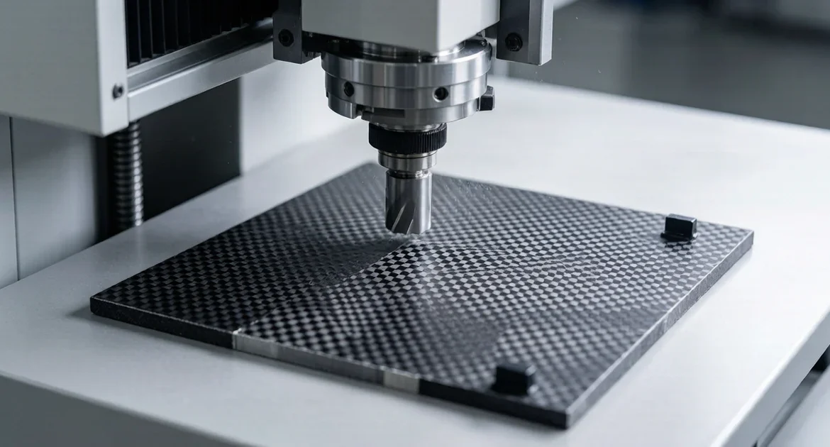
La découpe de profilés et le fraisage CNC définissent le contour d'une pièce en fibre de carbone — la géométrie du périmètre externe qui détermine la forme. Il s'agit de l'opération de traitement la plus courante et celle où le choix de l'outillage a le plus grand impact sur la qualité de la pièce.
Pièces généralement soumises à la découpe de profilés et au fraisage :
- Cadres en fibre de carbone — cadres de drone, cadres structurels, cadres de montage
- Plaques arrière et plaques frontales — panneaux plats en fibre de carbone avec géométrie de découpe
- Plaques de couverture et panneaux adaptateurs — composants définis par leur contour avec des dimensions externes spécifiques
- Cadres de plaques d'immatriculation — pièces critiques sur le plan esthétique où la qualité des arêtes est directement visible
- Plaques structurelles — plaques porteuses avec des contours externes spécifiques
La variable critique dans le fraisage CNC de la fibre de carbone est la direction de la trajectoire d'outil par rapport au stratifié. Le fraisage contre la direction des fibres du côté de la sortie peut soulever le pli externe et provoquer un écaillage des arêtes. Un bon fraisage prend en compte la coupe en avalant par rapport à la coupe conventionnelle, l'angle d'engagement de l'outil, et la présence éventuelle de rayons internes serrés qui concentrent les contraintes. Chez GRAN, les paramètres de fraisage — y compris l'avance, la vitesse de broche et la profondeur de coupe — sont définis en fonction du stratifié en fibre de carbone spécifique, et non d'un préréglage composite générique.
2. Perçage et fraisurage : Contrôle de l'éclatement et du délaminage
Le perçage est l'opération où apparaissent la plupart des problèmes d'usinage de la fibre de carbone. Lorsque le foret sort du côté arrière du stratifié, le pli externe non soutenu peut se délaminer — se détachant de la couche située en dessous au lieu d'être coupé proprement. C'est ce qu'on appelle le délaminage par poussée, et c'est le problème de qualité le plus courant dans le perçage de la fibre de carbone.
Pièces nécessitant un perçage et un fraisurage :
- Plaques de montage avec motifs de trous pour fixations
- Supports et points de fixation avec assemblage par boulonnage traversant
- Panneaux nécessitant un logement de vis affleurant via des trous fraisés
- Bras de drone et plaques de cadre avec motifs de trous d'allègement
- Couvercles OEM personnalisés avec trous de passage pour quincaillerie
GRAN gère le perçage de la fibre de carbone avec une géométrie de foret spécifique à l'application — généralement une conception en pointe de lance ou à pointe centrale avec un angle de pointe aigu qui minimise la force de poussée à la percée. Une plaque de support sacrificielle sous la pièce soutient le côté de sortie et empêche le pli externe de se soulever. Pour le fraisurage, le diamètre du trou pilote et l'angle de fraisure sont adaptés à la spécification de la fixation afin d'éviter la fissuration du stratifié autour de l'épaulement de la fraisure.
3. Détourage des arêtes et usinage de fentes : Travail de détail définissant l'ajustement et l'apparence
Après la découpe du profil principal et le perçage des trous, de nombreuses pièces en fibre de carbone nécessitent un travail de détail supplémentaire — fentes, découpes de ventilation, caractéristiques d'interface et affinage des arêtes pour l'ajustement lors de l'assemblage.
Pièces nécessitant un détourage des arêtes et un usinage de fentes :
- Bras en fibre de carbone — bras de drone, bras de support, bras structurels avec caractéristiques de fentes
- Éléments de support avec fentes d'interface et caractéristiques de positionnement
- Panneaux avec motifs de ventilation, fentes de passage de câbles ou découpes d'allègement
- Panneaux personnalisés avec géométrie de fente non standard pour des assemblages OEM spécifiques
L'usinage de fentes dans la fibre de carbone présente un défi unique : l'outil est engagé des deux côtés de la coupe, ce qui double la force de coupe par rapport à une coupe de périmètre. Les fentes étroites à rapport d'aspect élevé nécessitent des avances réduites et peuvent exiger une passe d'ébauche suivie d'une passe de finition pour maintenir une largeur de fente constante. Le détourage des arêtes — l'affinage de la finition du périmètre après la découpe du profil principal — élimine tout micro-écaillage et amène l'arête au niveau de qualité spécifié.
4. Traitement de surface et des arêtes : Finition pour une présentation propre
Les pièces en fibre de carbone destinées à des applications visibles — cadres de drone, composants d'articles de sport, cadres de plaques d'immatriculation — nécessitent plus qu'une simple géométrie précise. La surface et les arêtes doivent se présenter proprement, sans bavures, sans arrachement de fibres ni traces de résine.
Le traitement post-usinage chez GRAN comprend :
- Nettoyage des arêtes — Élimination des micro-bavures et des fibres libres laissées par l'opération de coupe. L'objectif est une arête lisse, uniforme au toucher et d'apparence soignée.
- Contrôle des bavures — Les bavures de fibre de carbone sont coupantes et abrasives. Un ébavurage contrôlé protège à la fois la pièce et toute personne qui la manipule en aval.
- Retouche de surface — Affinage léger de la surface pour éliminer tout résidu de résine ou marque de fluide de coupe sans poncer à travers le pli externe ni altérer le motif de tissage visible.
- Préservation du stratifié — Toutes les étapes de finition sont conçues pour nettoyer la pièce sans compromettre la liaison du stratifié ni exposer les fibres brutes sur les bords.
Quelle méthode de traitement correspond à votre pièce en fibre de carbone
La plupart des pièces en fibre de carbone nécessitent plus d'une opération de traitement. Un cadre de drone, par exemple, commence par un profilage, puis est percé pour les trous de montage, ébavuré sur les bords des bras, et terminé par un traitement de surface et des bords. Le tableau ci-dessous indique les méthodes applicables à chaque catégorie courante de pièces en fibre de carbone.
| Catégorie de pièce | Profilage / Détourage | Perçage | Rainurage / Ébavurage | Finition de surface |
|---|---|---|---|---|
| Cadres et bras de drones | \u2713 | \u2713 | \u2713 | \u2713 |
| Plaques arrière et plaques frontales | \u2713 | \u2713 | \u2713 | |
| Supports de montage | \u2713 | \u2713 | ||
| Panneaux ventilés | \u2713 | \u2713 | \u2713 | \u2713 |
| Cadres de plaques d'immatriculation | \u2713 | \u2713 | \u2713 | |
| Pièces pour produits sportifs | \u2713 | \u2713 | \u2713 | \u2713 |
| Capots OEM et plaques adaptatrices | \u2713 | \u2713 | \u2713 |
6. Comment Gran évalue les projets en fibre de carbone avant leur mise en production
Chaque projet en fibre de carbone passe par une revue structurée avant le début de l'usinage. Ce processus identifie les méthodes de traitement appropriées, détecte les problèmes liés au stratifié dès le départ et prévient les défauts de qualité dont la correction est coûteuse en aval.
- Revue de la géométrie de la pièce et du stratifié — Nous examinons le contour de la pièce, l'épaisseur, l'orientation des plis et la géométrie globale. Cela détermine les opérations de traitement nécessaires et signale toute caractéristique — sections très étroites, rayons internes serrés ou zones minces non supportées — pouvant nécessiter une manipulation particulière.
- Vérification de l'implantation des trous et des caractéristiques — Les positions de perçage, les diamètres des trous, les spécifications de fraisage et les dimensions des rainures sont vérifiés par rapport au plan. L'espacement entre les trous et la proximité des bords de la pièce sont évalués pour déterminer le risque d'éclatement.
- Sélection de l'itinéraire de traitement — Sur la base de la revue géométrique et des caractéristiques, nous déterminons la séquence des opérations : profilage d'abord, puis perçage et fraisage, ensuite ébavurage et rainurage, puis finition de surface. La séquence est importante car les effets thermiques et les forces de serrage peuvent varier selon l'ordre des opérations.
- Alignement des attentes concernant la finition des bords — Nous confirmons si la pièce est fonctionnelle (support interne avec bords cachés) ou critique sur le plan esthétique (bras de cadre de drone visible). Cela détermine la norme d'ébavurage des bords et de finition de surface.
- Validation des échantillons — Un petit lot d'échantillons est usiné, inspecté et examiné pour vérifier la qualité des bords, l'état des trous, la précision dimensionnelle et l'apparence de surface avant le début de la production complète.
Pour le flux de travail complet du projet, de la revue du plan à la livraison, consultez notre Aperçu du processus d'usinage CNC.
Lancez votre projet de traitement de fibre de carbone
Si vous avez une pièce en fibre de carbone nécessitant une découpe de profil, un usinage CNC, un perçage, un fraisage ou une finition des bords, GRAN INDUSTRIES SDN. BHD. est équipé pour la prendre en charge — de la validation du prototype à la production en série.
Envoyez votre dessin, échantillon de référence ou cahier des charges à info@gran.my ou contactez-nous à +60 10-881 2868. Incluez la géométrie de votre pièce, l'épaisseur du matériau, les détails des trous et des caractéristiques, ainsi que vos exigences quantitatives. Notre équipe d'ingénierie examine chaque demande et retourne un devis avec la méthode de traitement recommandée et les délais.
Visitez notre Page de service Traitement de la fibre de carbone pour plus de détails sur les capacités, les catégories de pièces et la planification de projet.
Foire Aux Questions
Q : La fibre de carbone peut-elle être usinée avec des outils CNC standard ?
Q : Qu'est-ce que le délaminage et comment le prévenez-vous lors de l'usinage de la fibre de carbone ?.
R : Le délaminage est la séparation des plis de fibre de carbone pendant l'usinage — le plus souvent lorsqu'un foret sort du côté arrière du stratifié et soulève le pli externe non supporté. Nous le prévenons grâce à la géométrie de l'outil (angles de pointe aiguisés qui réduisent la force de poussée), des plaques de support sacrificielles qui soutiennent le côté de sortie, des vitesses d'avance contrôlées et un serrage qui maintient le stratifié stable tout au long de la coupe.
Q : Comment obtenez-vous une finition de bord nette sur les pièces en fibre de carbone usinées ?.
R : Des bords nets résultent de la combinaison d'une direction de trajectoire d'outil correcte par rapport au stratifié, d'une géométrie d'outil appropriée, d'une stratégie de fraisage en avalant ou en opposition, et d'une passe de finition après la coupe de profil grossière. Pour les pièces critiques sur le plan esthétique, nous ajoutons un ébavurage dédié des bords et un contrôle de l'ébavurage afin d'éliminer tout micro-écaillage et de présenter un bord uniforme.
Q : Quels types de pièces en fibre de carbone GRAN traite-t-il ?.
R : Nous traitons les cadres et bras de drones, les plaques arrière, les plaques frontales, les plaques de couverture, les supports de montage, les cadres de plaques d'immatriculation, les plaques structurelles, les composants de produits sportifs, les panneaux adaptateurs et les pièces OEM personnalisées en fibre de carbone. Les échantillons prototypes et les lots de production sont tous deux pris en charge.
Q : Fournissez-vous le matériau en fibre de carbone ou le client le fournit-il ?.
R : Nous pouvons travailler dans les deux cas. Si vous disposez d'un stratifié en fibre de carbone spécifié ou de feuilles pré-achetées, nous pouvons traiter votre matériau. Si vous préférez que nous nous procurions le matériau, nous pouvons acquérir des feuilles de fibre de carbone correspondant à vos exigences d'épaisseur, de tissage et de qualité. Discutez de l'approvisionnement en matériau lors de l'étape du devis afin que nous l'incluions dans le plan de projet.
Méthodes de traitement de la fibre de carbone : découpe de profil, détourage, perçage et ébavurage des bords pour pièces composites personnalisées | GRAN.