Pockets are common in CNC machined parts because they reduce weight, create mounting space, clear assemblies, and make room for nested features. They can look straightforward in a 3D model, but pocket geometry often affects machining strategy more than expected. Depth, floor condition, internal radii, wall support, and access for cutting tools all influence how the part is quoted, machined, and inspected.
Many drawing issues begin when a pocket is dimensioned only by width, length, and nominal depth. That may not be enough if the pocket floor supports another component, controls clearance for a mating part, or must maintain a specific finish or flatness level. A deep cavity with limited access may also behave very differently from a shallow pocket on an open face, even if both features appear simple in CAD.
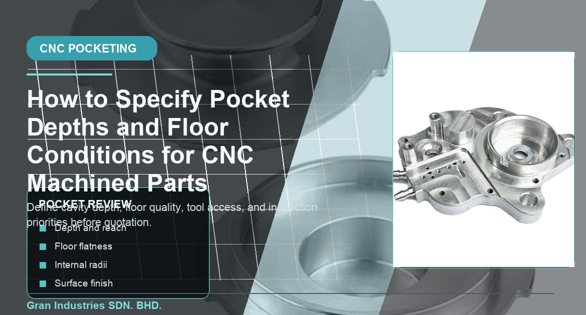
At Gran Industries, pocket review is part of the broader drawing-review process for custom CNC machined parts. The practical goal is to identify which aspects of the pocket are truly functional and which can follow standard machining capability so quotation and production planning stay realistic.
Start by defining what the pocket needs to do
Not every pocket is functionally important in the same way. Some exist only to remove material. Others provide space for electronics, seals, inserts, fasteners, mating parts, or fluid paths. A pocket floor may carry a component, act as a datum surface, or simply create clearance. Until the drawing clarifies that purpose, the supplier has to make assumptions about what needs control.
Tra le domande iniziali più utili si possono citare:
- Is the pocket only for weight reduction or does it locate another component?
- Does the floor need a controlled finish, flatness, or thickness relationship?
- Do the side walls matter for fit, or only the open cavity size?
- Does the pocket interact with holes, slots, threads, or mounting faces?
- Is the same feature requirement needed for prototype and repeat production?
When the pocket function is defined clearly, the machining team can separate critical requirements from general stock-removal geometry.
Why pocket details affect CNC machining quotes
Pocket machining can change tool selection, reach, step-over strategy, cycle time, and setup planning. A shallow open pocket may be easy to machine with a rigid tool and broad cutter engagement. A deeper cavity may require smaller tools, reduced step-down, more careful chip evacuation, and extra finishing passes on the floor or walls. If the RFQ only shows nominal geometry, the quotation may not capture the actual process effort.
This is why pockets should be reviewed during revisione dei disegni prima dei preventivi di lavorazione CNC e della produzione. If the design intent is not explicit, the supplier may need to assume a conservative process or return with questions after quotation has already started.
Pockets usually deserve closer review when the part includes:
- Deep cavities relative to pocket width
- Floor surfaces that support another part
- Thin surrounding walls or webs
- Nested steps, islands, or multi-level cavity geometry
- Very small internal corner radii
- Pockets combined with precision holes, slots, or threaded features
Depth alone does not describe the manufacturing challenge
Pocket depth is important, but it should not be reviewed in isolation. The same depth can be easy in one layout and difficult in another depending on the tool access path, internal radii, pocket opening, and nearby geometry. A relatively modest depth may still require a narrow tool if the opening is restricted. A larger open pocket may be machined efficiently even when it is deeper.
Una richiesta di offerta più rigorosa di solito chiarisce:
- Nominal pocket depth and allowable depth tolerance
- Whether the floor is function-critical or only nominally located
- Whether the walls, floor, or both need finishing control
- Whether the pocket includes steps, islands, or local reliefs
- Whether stock condition or pre-machined references affect the depth requirement
This makes the feature easier to quote as a manufacturing task instead of just a geometric void.
Floor condition can matter as much as cavity size
A pocket floor may need to do more than sit at a certain depth. It may support a component, control adhesive thickness, act as a stop surface, seal against a gasket, or establish a local datum. In those cases, the floor condition may be more important than the side-wall appearance of the pocket itself.
If the floor matters, the drawing should clarify whether the key requirement is:
- Flatness across the floor
- Parallelism to a datum face
- Surface finish for contact or sealing
- Step height relative to another feature
- Local support pads versus the full floor area
Without that distinction, a supplier may assume a standard machined floor is acceptable when the part actually needs more controlled finishing on a local contact surface.
This links directly to flatness and parallelism planning for CNC machined parts when the floor functions as a controlled support or datum relationship.
Internal corner radius and tool access should be realistic
Pockets nearly always involve internal radii because CNC tools are round. If the model shows sharp internal corners but the drawing does not allow a practical radius or corner relief, the part may be harder to machine than expected or may require a feature adjustment during review. This becomes more important as pockets get smaller, deeper, or more crowded by nearby features.
Helpful clarifications include:
- Minimum acceptable internal radius
- Whether local reliefs are acceptable at corners
- Whether the pocket needs to accept a square mating component
- Whether sidewall finish is secondary to floor quality
- Whether tool entry is available from an open face or a limited opening
If the function allows a practical internal radius, machining can usually stay more stable and efficient. If a special corner condition matters, the drawing should say so directly instead of leaving the supplier to infer it from the model.
Pockets can change part stiffness and local distortion behavior
Large or deep pockets remove stiffness from the part. That can affect how the workpiece responds to clamping, cutting forces, and finishing passes. A pocket that seems harmless on a thick block may create movement if it leaves a thin floor, long unsupported walls, or narrow webs connecting the remaining material.
This is one reason pocket planning often overlaps with the same concerns seen in thin-wall CNC machined parts. If the pocket leaves low-stiffness geometry, the RFQ should help the supplier understand which surfaces matter most and which areas can follow standard machining capability.
Useful review questions include:
- Does the pocket leave a minimum floor thickness that matters to part function?
- Are the surrounding walls cosmetic, structural, or fit-critical?
- Will the part be clamped near the cavity during machining?
- Does the floor need a finishing pass after most stock removal is complete?
- Are there nearby features that depend on the pocket staying stable?
Material choice affects pocket-machining behavior
Different materials respond differently to pocketing. Aluminum may machine efficiently but can still move when large amounts of material are removed. Stainless steel may demand more care around cutting forces and heat. Copper alloys can change tool behavior at edges and surfaces. Engineering plastics may need careful support because clamping and heat can affect shape. Carbon fiber processing introduces its own concerns around laminate support, dust control, and edge condition.
That is why pocket requirements should stay connected to material planning. Projects involving lavorazione CNC della lega di alluminio, lavorazione CNC dell'acciaio inossidabile, copper and copper-alloy machining, lavorazione della plastica, o lavorazione della fibra di carbonio should not assume that one cavity strategy suits every material equally well.
Surface finish and edge condition may need to be tied to the pocket
A pocket may have a floor that needs a specific finish while the walls only need standard machining. In other cases, burrs at the pocket edge or step transitions may affect assembly, cable routing, or cosmetic appearance. If the RFQ does not connect finish and edge requirements to the actual feature, the supplier may not know which surfaces deserve more attention.
Questo è strettamente legato a surface finish planning e note sulla rottura del bordo e sulla sbavatura for CNC machined parts. A pocket feature should not be treated as purely dimensional if the same area also controls contact, appearance, or safe assembly.
Inspection should match the feature’s acceptance role
Pocket inspection can focus on different things depending on function. Some parts need only a depth check and basic cavity size confirmation. Others need floor flatness, positional relationships to datums, or verification that the cavity accepts another part correctly. If inspection priorities are unclear, the measurement effort may not align with the reason the pocket exists.
La pianificazione delle ispezioni dovrebbe chiarire:
- Which pocket dimensions determine acceptance
- Whether the floor is checked for depth only or also for geometry condition
- Which datum reference should be used
- Whether local support pads or the full floor need evaluation
- Whether the feature is part of ispezione del primo articolo
That helps inspection stay efficient and function-focused rather than measuring the entire cavity to the same level by default.
What to include in an RFQ when pocket details matter
For CNC machined parts with important pocket features, the quotation package is usually stronger when it includes:
- Disegno 2D e modello 3D, se disponibile
- Clear pocket depth and tolerance values
- Notes explaining whether the floor is functional, cosmetic, or clearance-only
- Minimum internal radius or acceptable relief strategy
- Material grade and order quantity
- Related surface finish and edge-condition notes
- Nearby hole, thread, slot, or datum relationships that affect the cavity
- Inspection or first article requirements tied to the feature function
This helps the supplier evaluate the cavity as part of a real production plan instead of just a removed block of material inside the model.
Clear pocket specifications support better machining outcomes
Pocket features often look secondary in a drawing, but they can influence tooling, cycle time, local stiffness, surface control, and acceptance criteria. When depth, floor condition, internal radius, and inspection priorities are defined clearly, the quote becomes more accurate and the machining process becomes more predictable.
If your custom CNC machined part includes deep pockets, stepped cavities, support floors, or clearance features, Gran Industries can review the drawing, material, tolerance approach, and production intent before quotation. You can also inviare i dettagli del progetto per la revisione quando siete pronti.